Motionet™
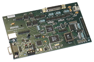
MN400
Multi-Axis Contouring Motion
Controller
With USB Interface
Motionet™ MN400
Multi-Axis Contouring Motion Controller
With USB Interface
|
MOTION CAPABILITIES:
|
 |
|
FEATURES:
|
SPECIFICATIONS:
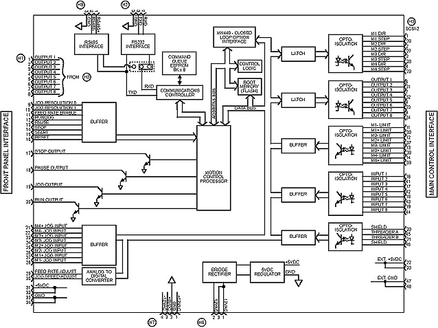
| Power Source | +5VDC ±5% |
| Current requirements | > 400mA |
| Step signals | 4 opto-isolated open collector |
| Direction signals | 4 opto-isolated open collector |
| Limit switch input signals | 8 TTL compatible active low |
| Safety shield interrupt input signal | 1 TTL compatible active low |
| Auxiliary input signals | 8 TTL compatible active low |
| Auxiliary output signals | 8 opto-isolated open collector |
| Jog inputs | 8 TTL compatible active low |
| Threading encoder inputs | 3 TTL compatible |
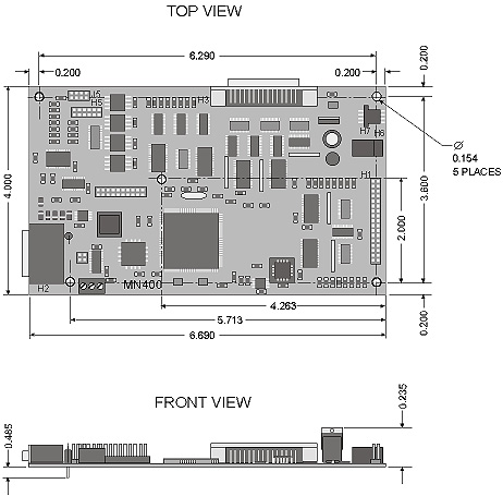
| Maximum step rate | 150,000 steps per second |
| Working temperature range | 32° F ~ 158° F (0° C ~ 70° C) |
|
|
|
|
|
|
|
|
MN400 Accessories
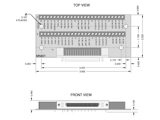
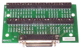
Converts the 50pin connector from an MN400 to screw terminals for easy wiring. Includes a 50 pin ribbon cable to attach.
DB-9 Cable
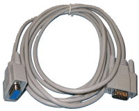
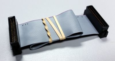
10' DB-9 Male to Female Cable used used to connect the MN400 to an open serial port on your PC.8 inch ribbon cable w/SCSI50 for MN400E
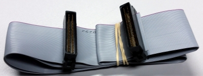
24 inch ribbon cable w/SCSI50 for DriveRack
MN400 Command Set
General: All MN400 parameters are 1 letter and are case insensitive. & indicates long integer. % indicates short integer.
Command Format: Command |
data | data | data | data | data | data
There should not be any spaces and the data is delimited using a comma.
e.g. m10000,20000,30000,-40000
| Command | Function |
|
A
centerx&, centery&, xdest&, ydest&, dir%
|
Moves tool along the path of an arc |
|
B
m1lash%, m2lash%, m3lash%, m4lash%
|
Sets the amount of backlash for each axis in steps |
|
C
port%, state%
|
Allows setting or resetting of the output ports |
|
D
m1lashdir%, m2lashdir%, m3lashdir%, m4lashdir%
|
Sets the initial state of the backlash direction all parameters are 1 or -1. |
|
E
m1&, m2&, m3&, m4&
|
Returns the total number of steps moved for each motor |
|
F
startspeed&, endspeed&, Accelrate&
|
Sets the ramping profile. Ramping is used during linear moves and jogging. |
|
G
res0&, res1&, res2&, res3&, step_per_inch&
|
Sets the number of steps to dispense upon jog button tap |
|
H
mode% (1 =shield mode, 0 = Feed hold)
|
Allows selection of shield interrupt mode or feedhold mode |
|
I
mode% (0 - absolute (default), 1 - incremental)
|
Allows you to select absolute or relative mode |
|
J
mode%0 ( 1 = jog mode, 0 = run mode)
|
Places the controller in jog mode or run mode |
|
L
m1&, m2&, m3&, m4&
|
Allows modification of the absolute count kept in memory . |
|
M
m1&, m2&, m3&, m4&
|
Performs a vector move. |
|
N
|
Returns number of steps not taken during previous move command. |
|
P
xmotor%, ymotor% (0 - M1, 1 - M2, 2 - M3, 3 - M4)
|
Selects the two motors to be used for circular interpolation. |
|
Q
|
Abort move that is in progress. |
|
R
|
Read the program stored in memory. |
|
S
|
Reports the status of the limit and auxiliary inputs. |
|
T
m1&, m2&, m3&, m4&, pulses&, offset%
|
Allows linear moves to be interpolated with external pulses. |
|
U
|
Runs a program stored in serial EEPROM. |
|
V
startspeed&
|
Sets velocity for linear & arc moves or sets external synchronization. |
|
X
multiplex%
|
Sets the resolution for multiplexing linear moves. |
|
Z
|
Enables writing of program to serial EEPROM. Terminate by sending EOF command (^D). |
|
?
rev%
|
Returns the current software version number. |
|
*
|
Request response from all devices. |
|
#
rate%
|
Sets the baud rate to the selected value (0 to 3 for 9600, 19200, 38400, 57600). |
Debugging Functions
| Command | Function |
| $ (Address - 0x2000) | Request the number of commands left to process in the DSP buffer. |
| % (Address - 0x2002) | Request the amount of space left in the DSP buffer |
| ! (Address - 0x2004) | Request the current buffer address in the DSP |
| ^ (Address - 0x002e) | Request the current value of the number of commands sent. |
| & (Address - 0x0030) | Request the current value of the number of commands processed. |

